________________________________________________________________________________________________
This chapter covers setting up the structure data for what was integrated into the cars hierarchy in Part 1.
________________________
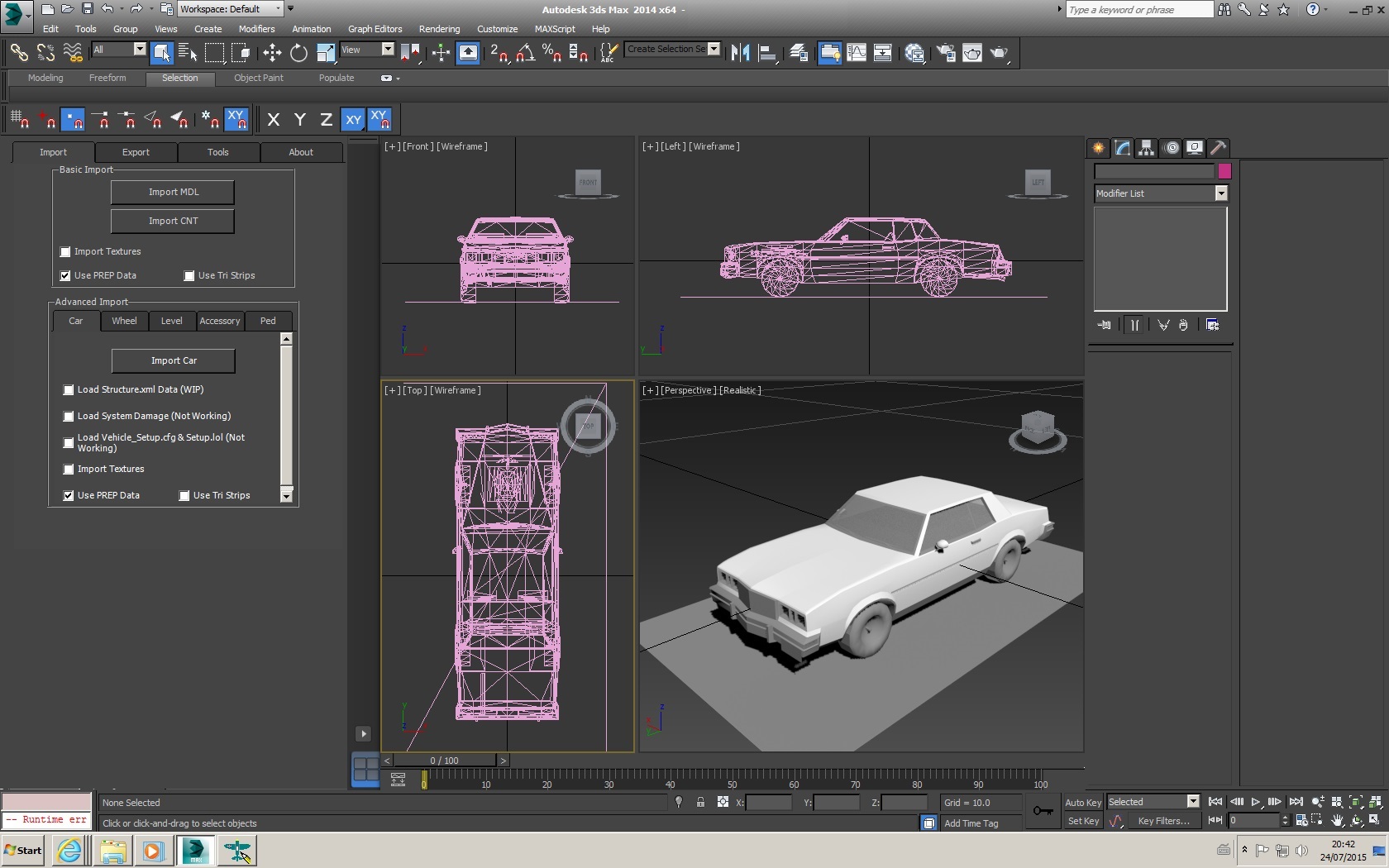
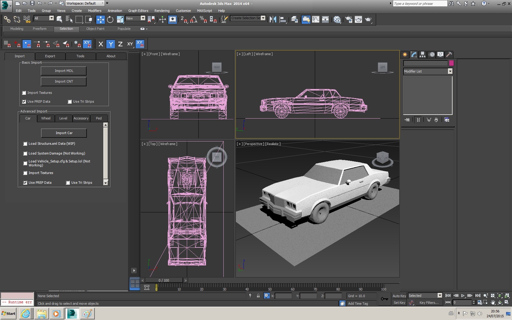
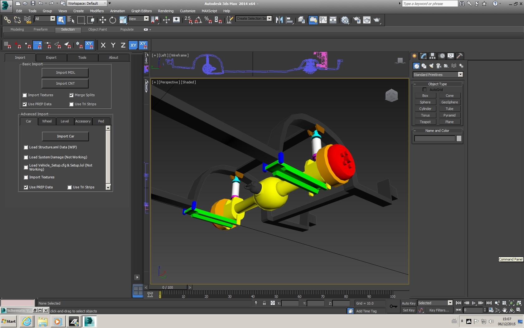
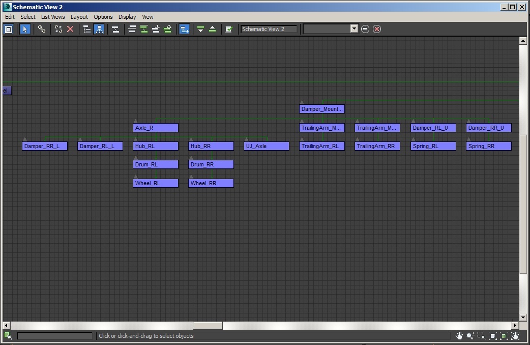
With everything that is needed for a basic car present in the scene, it is time to get the car structure setup, so the MaxScript can write the structure.xml for you when you export the car.
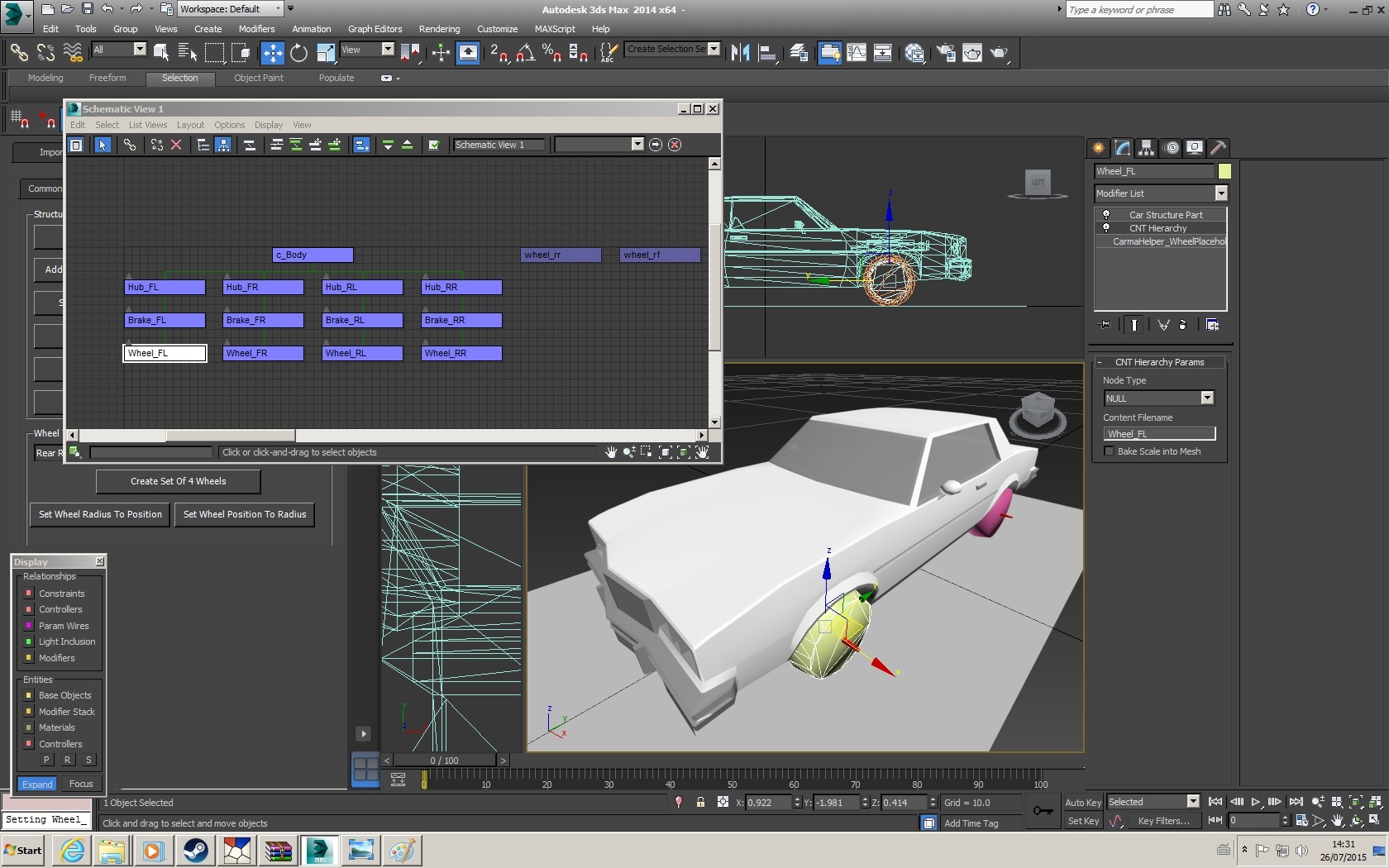
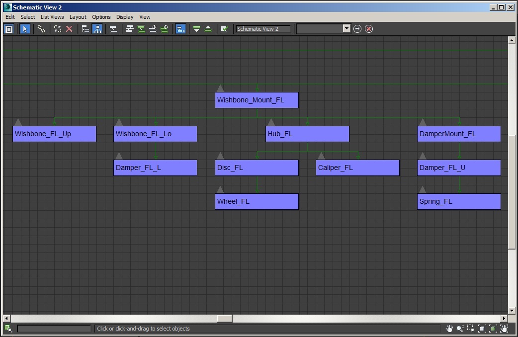
The first step is to setup the CNT Hierarchy data and add structure data to all necessary parts.
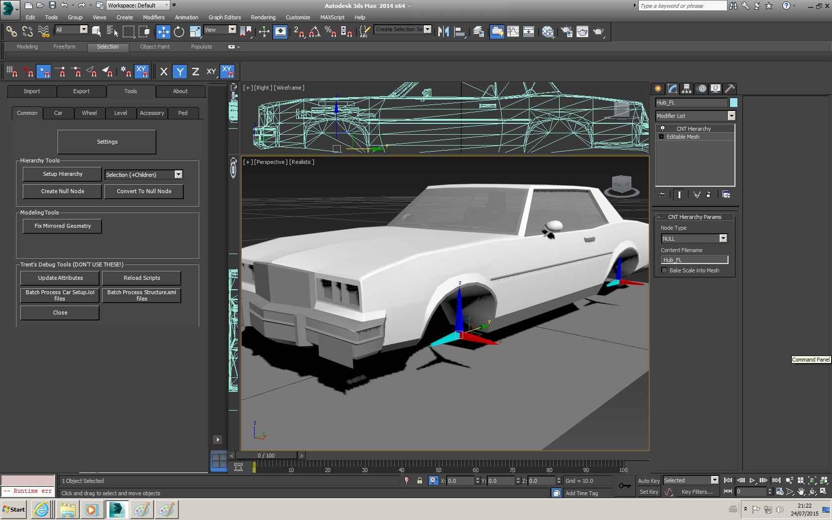
- Select the car body (c_Body)
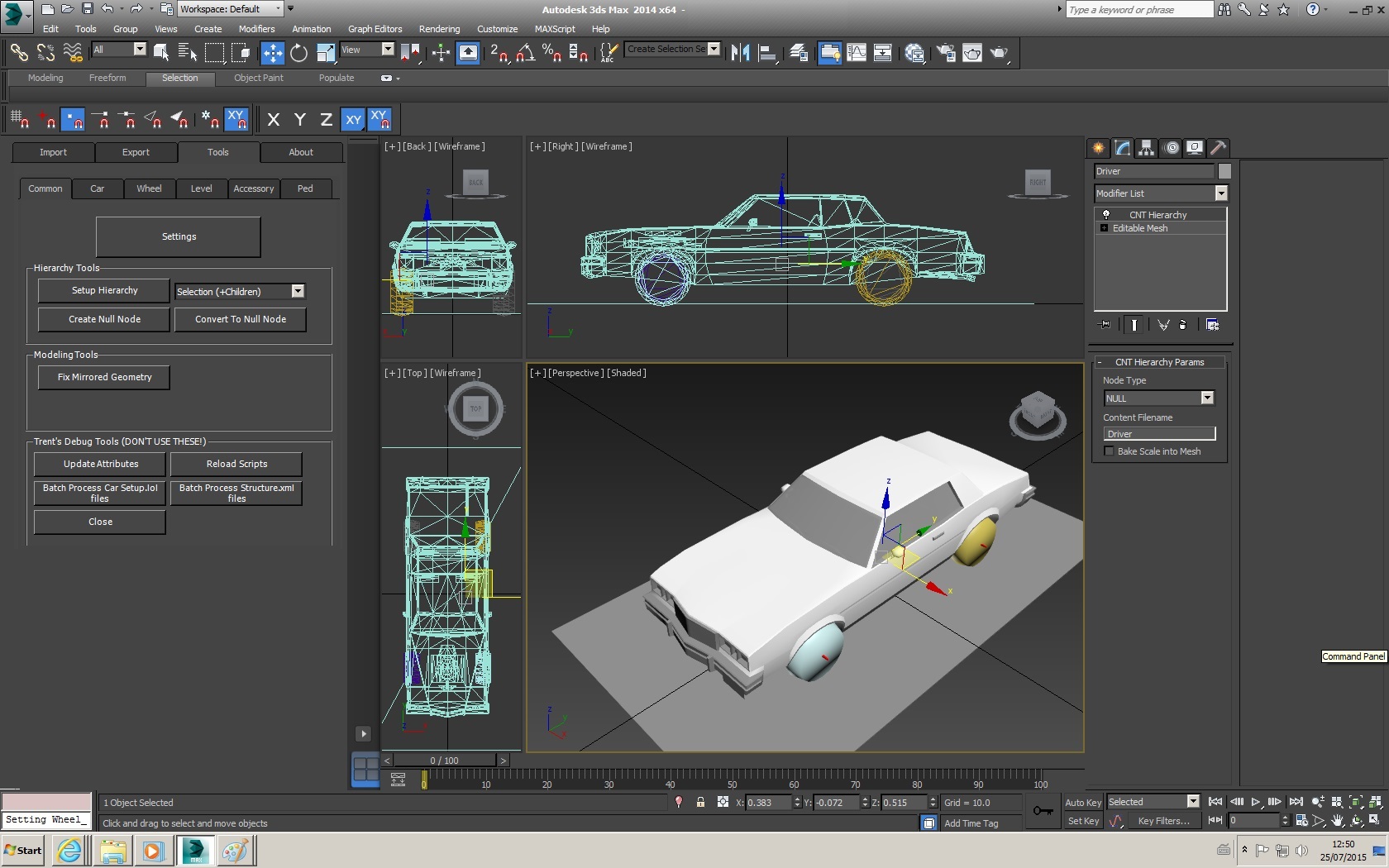
- Navigate to the ‘Tools’ -> ‘Common’ section of the Maxscript and press 'Setup Hierachy’**
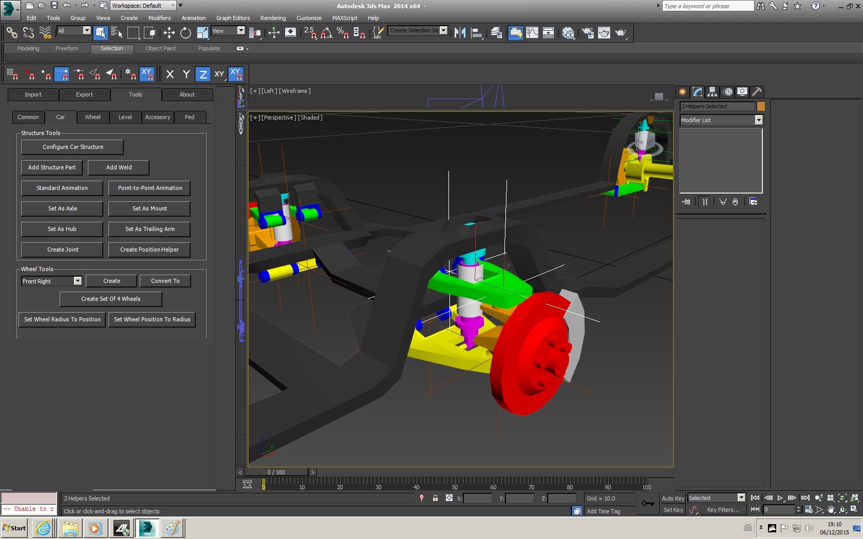
- Navigate to the ‘Tools’ -> ‘Car’ section of the Maxscript and press ‘Configure car structure’
Note:
These tools should only usually be used when the root node of the car is selected (Car Body model /c_Body). - The 'Setup Hierachy’ tool will go through every part in the hierarchy and add CNT hierarchy modifiers to it, unless you've changed the settings in the dropdown to 'Selection only'
- The ‘Configure car structure’ tool will add basic structure modifiers to all parts (if not already present). On more complex cars, such as the official cars or my own main cars this would take the Maxscript several minutes, as these operations are being conducted on 100 to 150 + parts.
Once this operation has completed, select the Driver Node, and delete the ‘Car Structure Part’ from the modifiers tab, then repeat this for the Exhaust Node(s). These Nodes serve only as points of reference for attaching external files and should never have structure data set.
** - You may notice that the 'setup hierarchy' has a drop down box next to it, with this you can set the tool to:
- Add CNT Hierarchy data to the selected part & all of its child parts
- Add CNT Hierarchy data to just the selected part
- Add CNT Hierarchy data to everything in the scene
________________________
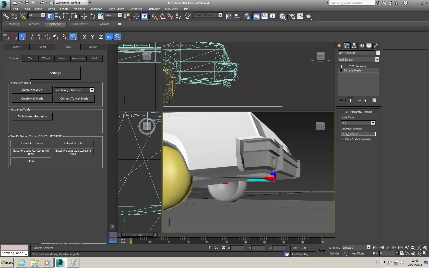
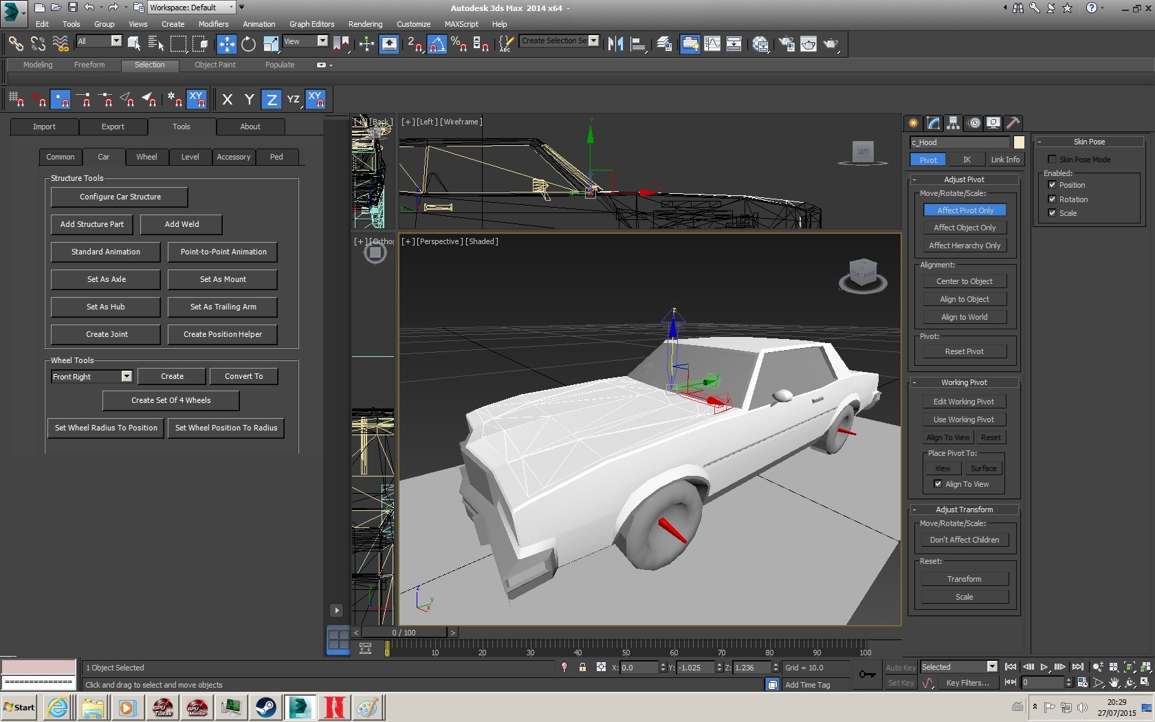
Now return to the car body (c_Body) model, and you will notice the following modifiers present under the modify tab in addition to what was present before
- Car Characteristics – Sets the basic car characteristics (defence, offence, etc) and should only ever appear on the root of the car (c_Body)
- Vehicle_Setup.cfg – Not currently working, ignore this
- Car Structure Part – Sets the structure data for that part
- CNT Hierachy – Required for export, sets the exported file name for model parts
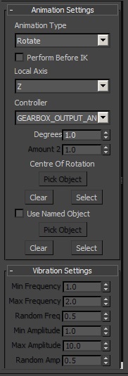
Select ‘Car Structure Part’, and you will notice a lot of drop down menus.
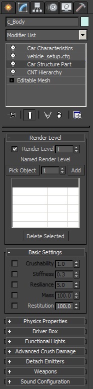
For the simplest of cars, we are only going to be making use of ‘Render Level’, ‘Basic Settings’, ‘Physics Properties’ & ‘Driver Box’. All of the drop downs will configure settings that will be wrote to the ‘Structure.xml’.
________________________
Render level sets at what distance a part is no longer rendered in-game, the Maxscript will default to ‘1’, which means always visible. You will need to select an appropriate value for all parts on your car that have Structure data.
On the official cars
- 1 = always visible, used by bodywork, wheels and weapons
Parts that use this level seem to be culled based on part volume relative to a 'far' camera distance. How 'far', depends on graphics settings
- 2 = rendering culled at far distance, usually used by windows, lights, engine, axles or mechanical parts on clear display
- 3 = rendering culled at close distance, usually used by all other mechanical parts (wishbones, hubs, mounts, shocks, coil springs, trailing arms, exhausts)
We will be setting a render level of:
- 3 for the Hubs & Brakes (despite them being Null Nodes with no actual geometry),
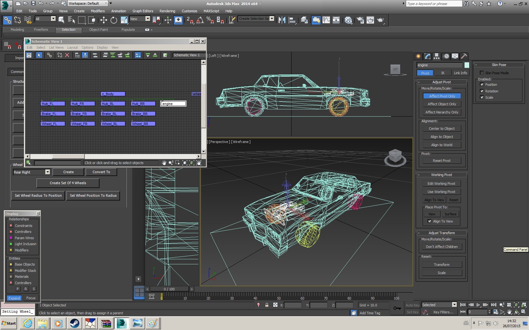
- 2 for the Engine Model
- 1 for the Body & Wheels
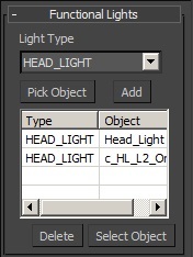
Additionally there is a ‘Named Render Level’ used for setting a render level for parts that don’t have any structure data, such as the Driver Node. There is no point in the driver being visible at a distance, when the player cannot see them. So with the car body (c_Body) selected, we will:
- Select ‘2’ on the Named Render Level
- Press ‘Pick Object’
- Click on the ‘Driver’ Node, the ‘pick object’ should now read ‘Driver’
- Press ‘Add’
The Named Render Level will generally not be used for anything else on the car.
________________________
The ‘Basic Settings’ literally control just that, the most basic of settings. For all parts (except wheels), a crushability value MUST be set
- 0.0 = Non deformable, part will take damage but won’t visually deform, normally used for mechanical parts & weapons
- >0.0 = deformable, amount of deformation will vary depending on if this is set to 1.0 or a smaller value
Most crushable parts (bodywork, windows, lights) have a crushability value of 1.0, and a ‘stiffness’ of 0.3, so enable these and set them appropriately. Trent has set the MaxScript so the default values for ‘Crushability’ and ‘Stiffness’ (when enabled) is 1.0 and 0.3 respectively.
Other settings (not usually used by the car body):
- Mass – Sets a mass for when a part detaches, this may result in damage to cars that hit this part. This value will also be deducted from the cars overall mass making it accelerate quicker
- Resiliance – Typically used by non-crushable parts (Weapons, Hubs, Suspension Mounts), this acts as a resistance to the part being moved when the car takes damage, stopping your wheels or engine from getting offset significantly in collisions. Usually a value of 1.0 is used on engines
- Restitution – Only used by wheels, not entirely sure what it does
________________________
This will add ‘Physics Properties’ to parts resulting in certain behaviours in-game, usually only used on:
- Wheels
- Hubs
- Tie/Track Rods
- Steering Wheel
- Brake Discs/Drums
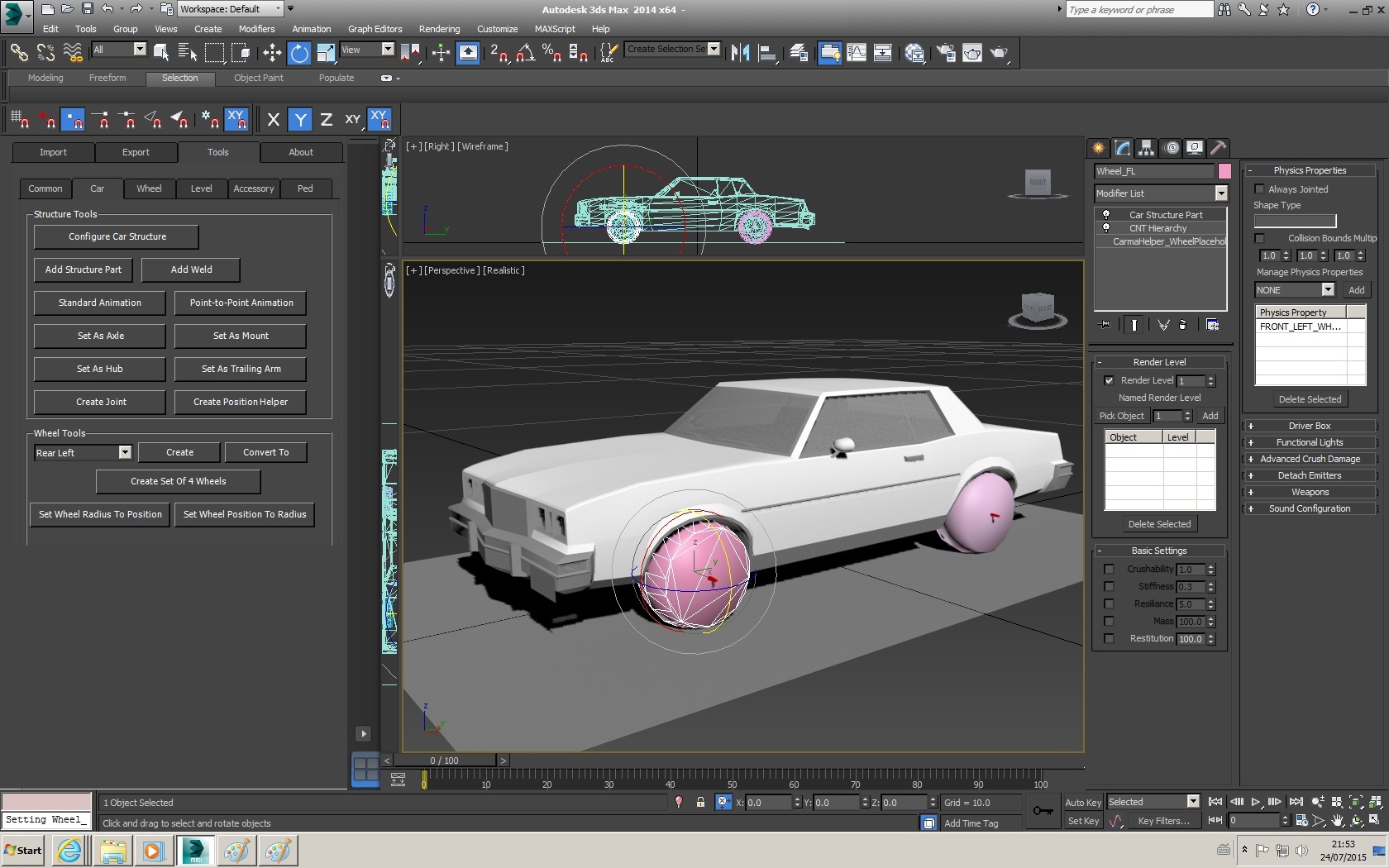
Collision shapes and bounding multipliers can also be set for parts that are especially high poly or have no geometry, and need simple collision shapes. The available shapes are ‘TIC_TAC_X’, ‘TIC_TAC_Y’ and ‘TIC_TAC_Z’. We will be setting a Collision shape of ‘TIC_TAC_X’ on each wheel when we get to them.
________________________
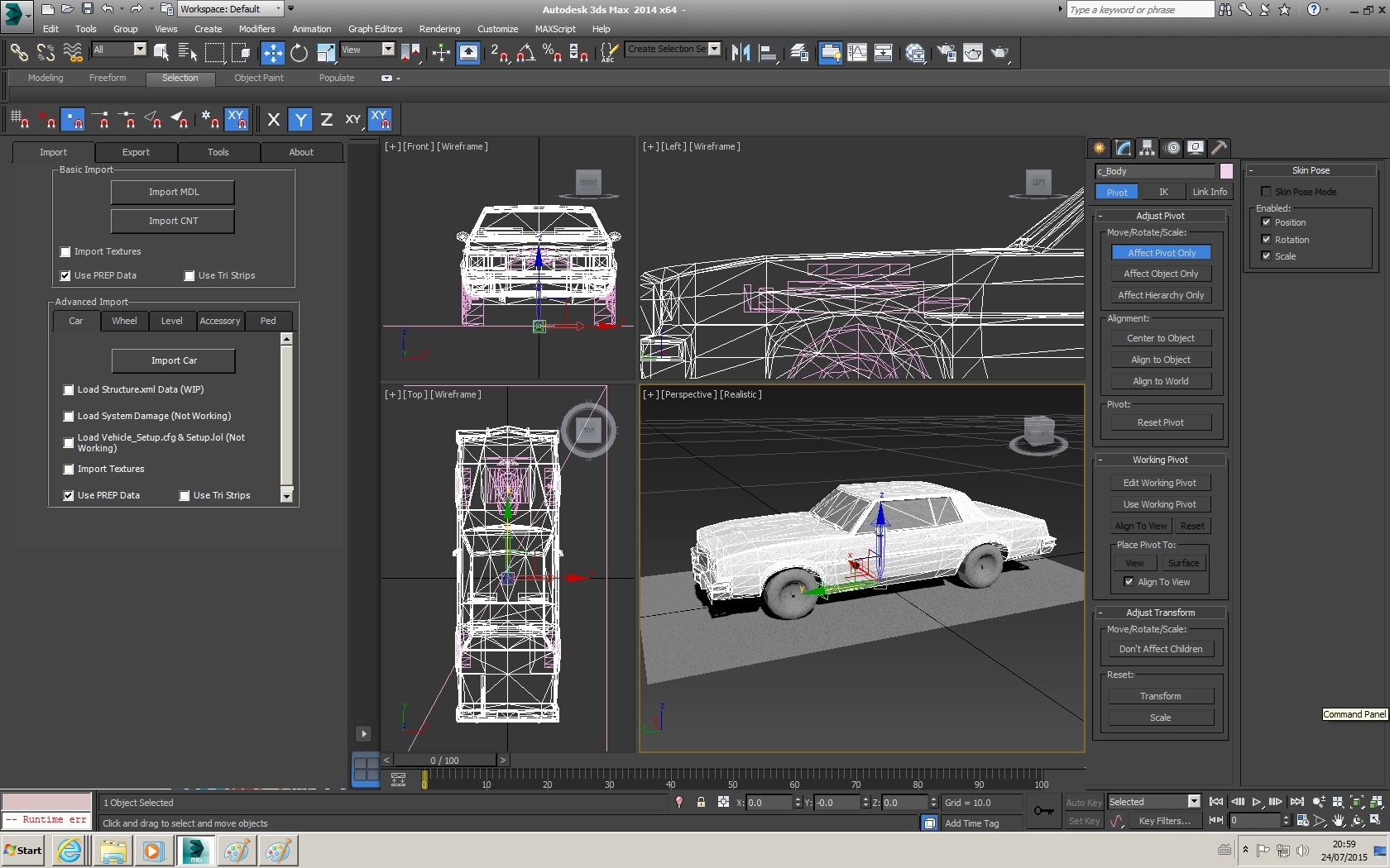
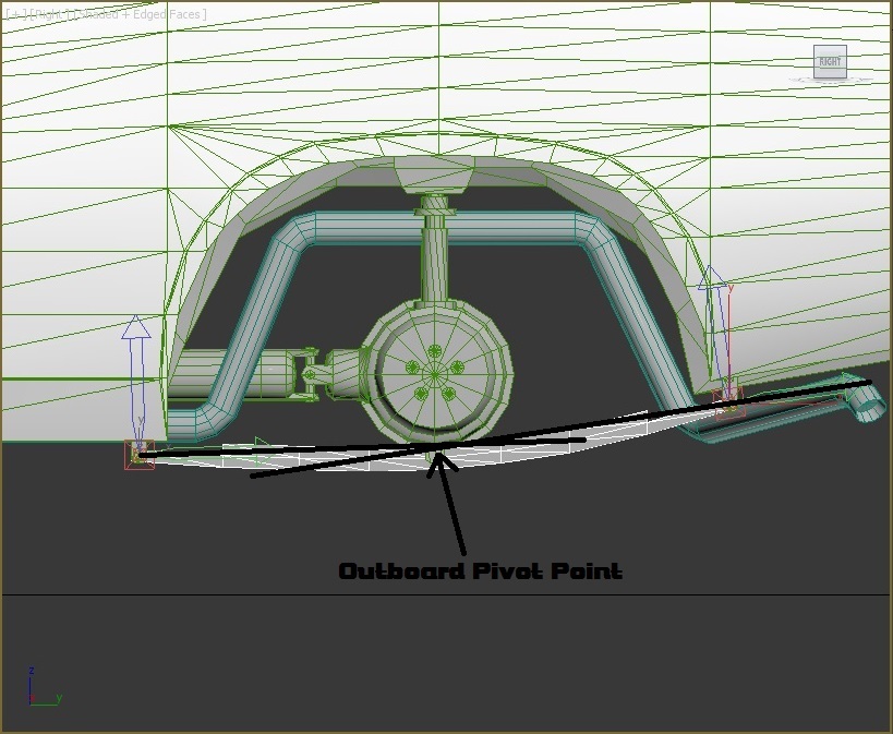
The Driver box is used to specify a box, which the driver model/s have to fit into, as this box crushes with the car – the driver will hunker/crouch down until they cannot shrink in volume any more, and are then replaced with the ‘Gibbed’ Organs. This is only ever used by the parent object of the driver node/s.
The Driver box is also used as the primary point of reference for positioning the in-car camera in-game. A manual offset from this point can be defined in the 'vehicle_setup.cfg' if the camera is not positioned where you want it. If a vehicle does not have a driver box, then the game might not allow the use of the in-car camera.
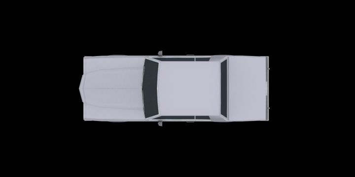
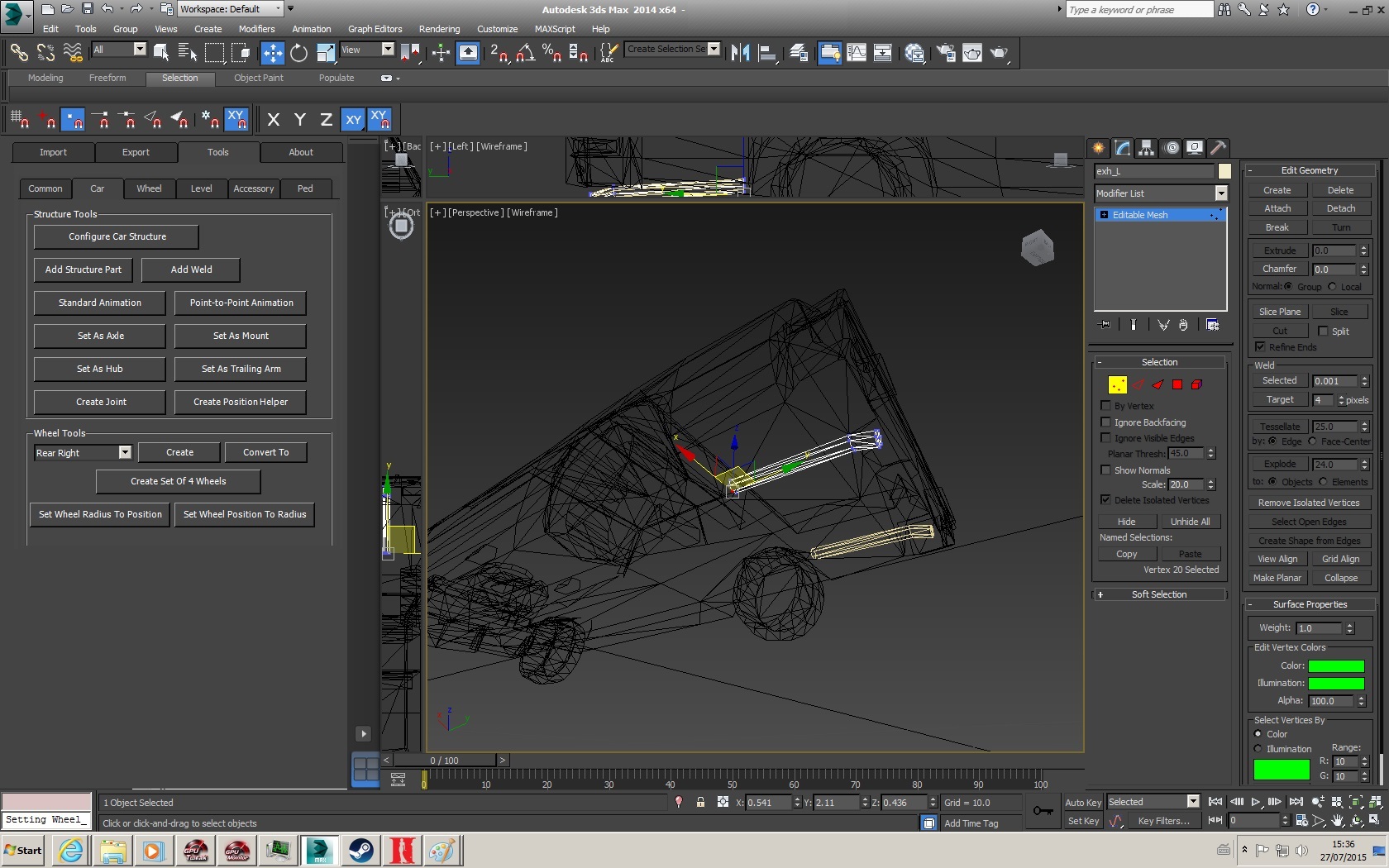
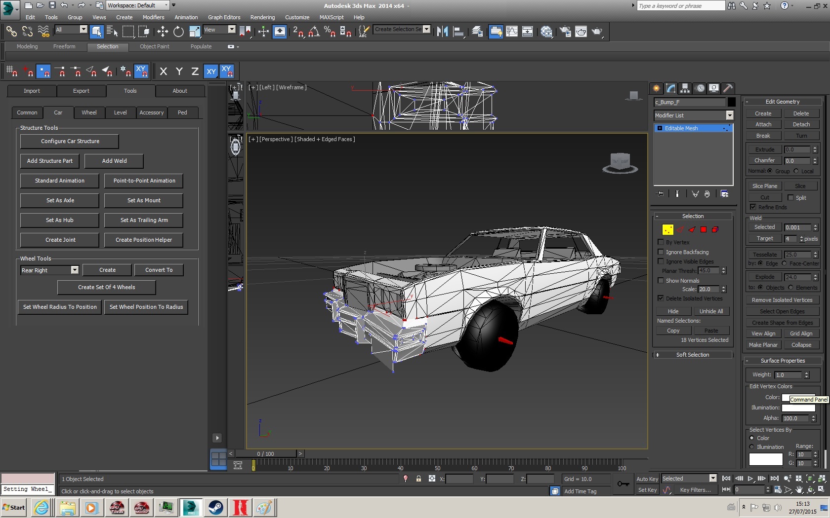
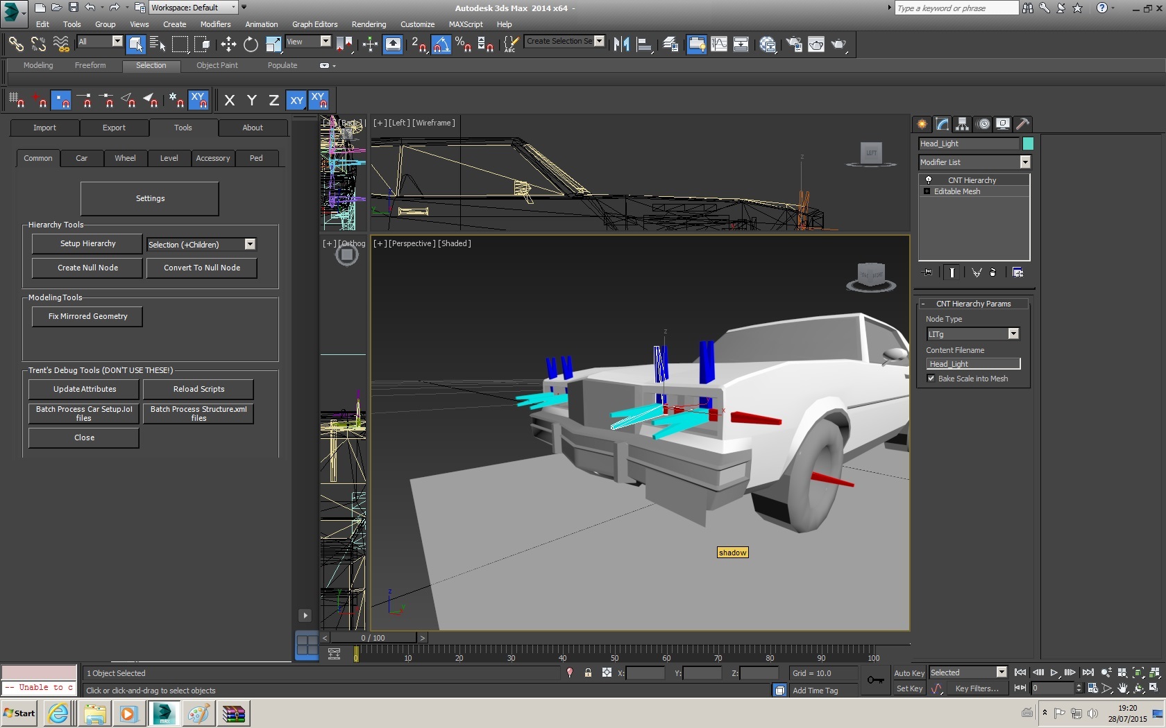
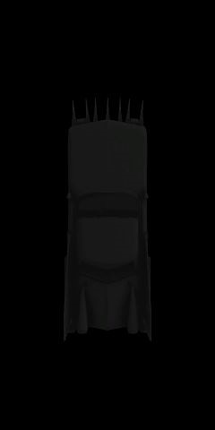
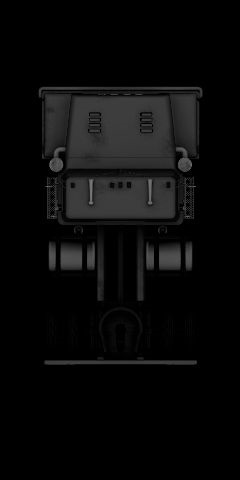
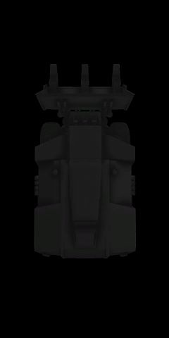
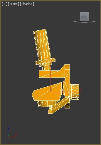
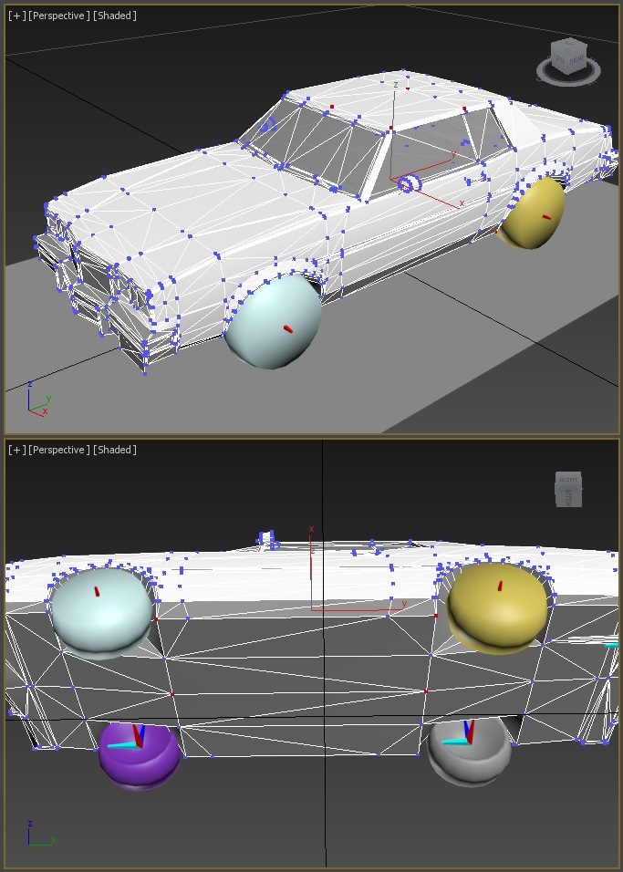
You need to select 8 vertices in the model and change the vertex colour to:
- - 255,0,255 (Pink) is used for Driver box 1
- - 0,255,255 (Cyan) is used for Driver Box 2 (only applicable if you’ve got 2 drivers – See Siamese Dream or Stiffshifter)
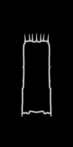
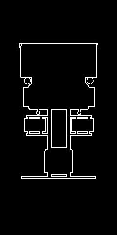
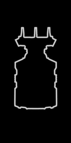
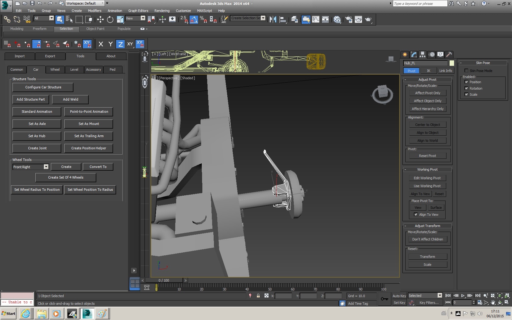
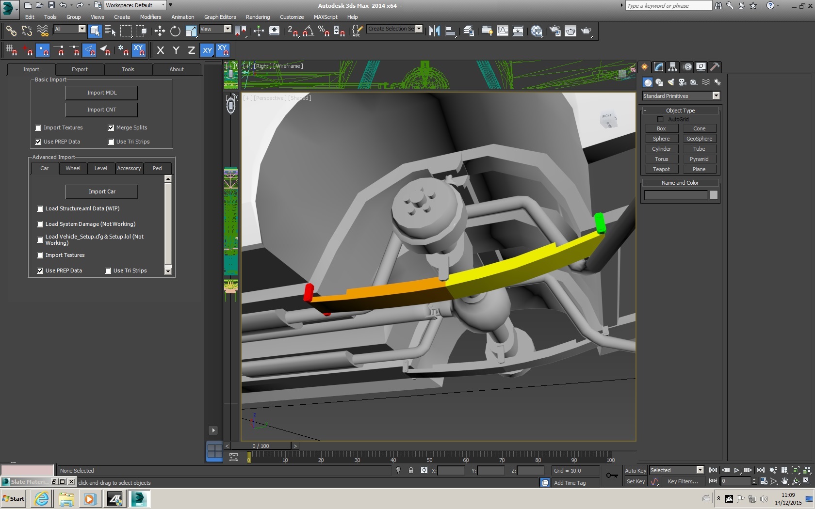
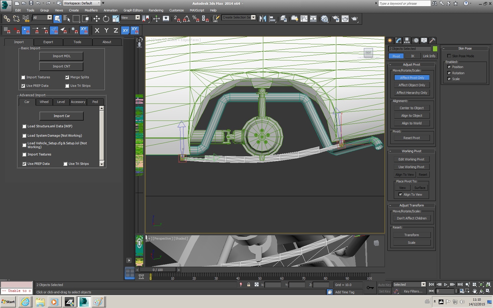
Below is an example of the 8 selected vertices (highlighted in red & taken from several angles) for the driver box
NOTE:
On a more complex model, the vertices used for the driver box will typically be part of the interior, rather than the exterior. Exterior vertices have been used in this instance as there are no suitable interior vertices.With the vertex colours set accordingly. To actually set the driver box, all you need to to do is navigate to the ‘Driver Box’ Section of the ‘Car Structure Part’ Modifier, and:
- Input the RGB Values of the driver box vertices in the first 3 boxes
255,0,255 (Pink) for Driver 1
000,255,255 (Cyan) for Driver 2 (If applicable)
- Press ‘Add’
- The driver box is now set
________________________
With the basic settings drop-downs that we're going to be using to set up this basic car covered. We will now setup the car Structure.
________________________________________________________________________________________________
Firstly, what we need to do, is setup the root of the car (c_Body)
________________________
Render Level:- leave at 1
- Set ‘Named Render Level’ For driver node at 2
Basic Settings:- Enable Crushability at 1.0
- Enable Stiffness at 0.3
Physics Properties:Driver Box:- Add a driver box that matches your 8 vertices, use 255,0,255 as the RGB Values
Next We will move onto the first Hub, ‘Hub_FL’.
________________________
Render Level:Basic Settings:- Enable Crushability and set to 0.0
- Enable Resiliance and set to 1.0
Physics Properties:- Set Collision Shape as ‘TIC_TAC_X’ (without the quotations)
- Add ‘FRONT_LEFT_POINT_OF_SUSPENSION’
- Add ‘FRONT_LEFT_POINT_OF_STEERING’
Note:
on the other hubs, ‘FRONT_LEFT’ will be the appropriate Physics property for that corner (FRONT_RIGHT, REAR_LEFT OR REAR_RIGHT). Also since we’re not modelling a car with 4 or rear wheel steering, the Rear Hubs (Hub_RL & Hub_RR) will not have a ‘POINT_OF_STEERING’ assigned to them!Welds:Now we need to ‘Weld’ the Hub to the ‘C_Body':
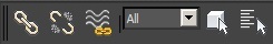
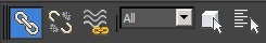
- Navigate to ‘Tools’ -> ‘Car’, and press ‘Add Weld’
A new modifier ‘Car Weld’ should now be present in the modifiers tab
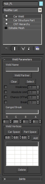
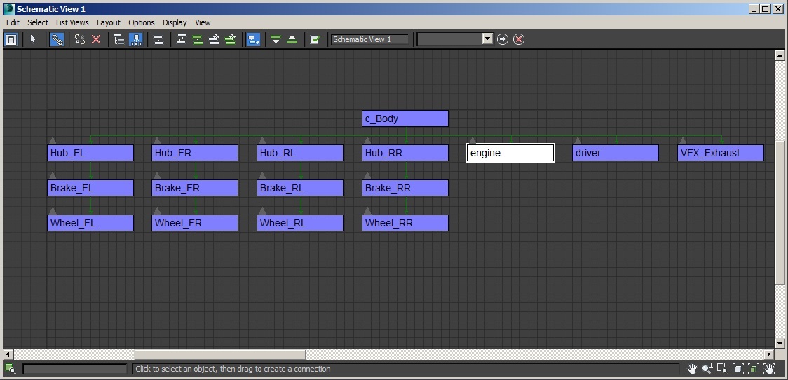
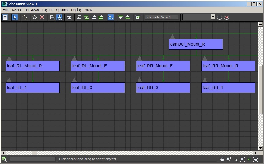
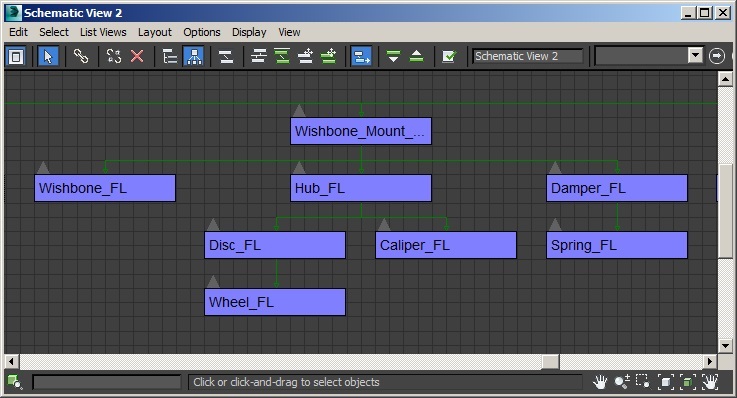
Welds set what parts are attached to in the hierarchy. This is typically the direct parent part or a sibling part (a part with the same parent as this part)
- Weld Name is optional, I usually set them to reflect what the weld does, in this case that would be ‘HubToBody_FL’
On the official cars, Weld Names are only used when setting up GangedBreaks (linking welds together so that when one breaks, the other will)
- Press ‘Weld Partner’ and then select the part to weld to – in this case the c_Body
‘Weld Partner’ should now display ‘c_Body’
- ‘Weakness’ will set the part as being detachable, the official cars typically use weld strengths of the following presets:
-1 to -8 (integer values only) – these reference preset weld stengths in-game, ‘-1′ is weakest, ‘-8′ is toughest
Hubs usually have a weld strength of -4 or -5, We’re going to set it at -5 for this car
- ‘Absolute Limit’, ‘Chance of Failure’ and ‘Break’ are more advanced weld parameters, which will not be used here
- As we are welding a part with no geometry, we need to add a vertex to the weld.
Leave the R,G,B,A values as 0,255,0,0
Press ‘Part Space’ -> ‘Add’ – this will add a vertex to the part at 0,0,0 in part-space
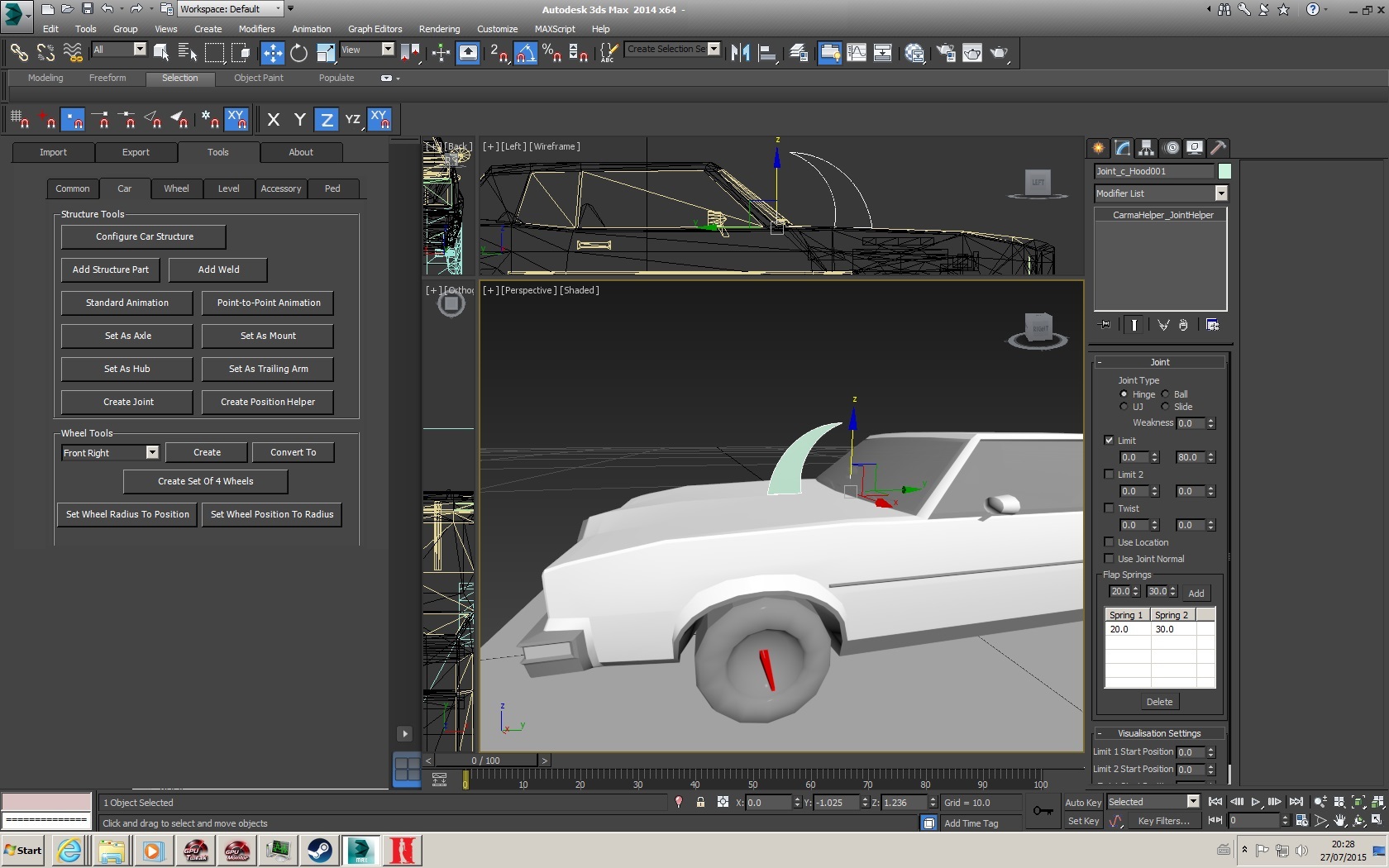
- The ‘Joints’ Menu only applies to jointed parts such as doors, hood, trunk, or any part than can dangle or move before breaking off
________________________
The Setup process for ‘Hub_FL’ should now be repeated for the other hubs (Hub_FR, Hub_RL, Hub_RR), but the physics properties will need to be appropriately assigned.
Hub_FL- ‘FRONT_LEFT_POINT_OF_SUSPENSION’
- ‘FRONT_LEFT_POINT_OF_STEERING’
Hub_FR- ‘FRONT_RIGHT_POINT_OF_SUSPENSION’
- ‘FRONT_RIGHT_POINT_OF_STEERING’
Hub_RL- ‘REAR_LEFT_POINT_OF_SUSPENSION’
Hub_RR- ‘REAR_RIGHT_POINT_OF_SUSPENSION’
________________________
Similarly to the hubs, we will begin the brake setup with Brake_FL.
Render Level:Basic Settings:- Enable Crushability and set to 0.0
Physics Properties:- Set Collision Shape as ‘TIC_TAC_X’ (without the quotations)
- Add the Physics property ‘FRONT_LEFT_POINT_OF_ROTATION’
Weld:Now we need to ‘Weld’ the Brake to the relevant Hub (Hub_FL):
- Navigate to ‘Tools’ -> ‘Car’, and press ‘Add Weld’
- Select ‘Weld Partner’, and pick Hub_FL
- Add a ‘Part Space’ Vertex at 0,0,0 (like we did with the Hub)
________________________
The Setup process for ‘Brake_FL’ should now be repeated for the other brakes (Brake_FR, Brake_RL, Brake_RR), but the physics properties will need to be appropriately assigned. On actual model parts, the ‘POINT_OF_ROTATION’ Physics Property will get the part to rotate at the same speed as the wheel.
Brake_FL- ‘FRONT_LEFT_POINT_OF_ROTATION’
Brake_FR- ‘FRONT_RIGHT_POINT_OF_ROTATION’
Brake_RL- ‘REAR_LEFT_POINT_OF_ROTATION’
Brake_RR- ‘REAR_RIGHT_POINT_OF_ROTATION’
________________________
Similarly to the hubs & brakes, we will begin with Wheel_FL. If you have created each wheel correctly (changing the drop-down to match the corner) or by using ‘create set of 4 wheels’, then each wheel should be correctly named, and already have the correct physics properties assigned.
Render Level:Basic Settings:- Do NOT enable crushability, stiffness or Resiliance
- Enable Restitution and set to an appropriate value, Light cars use 1.0, Trucks use 2.0, so We’ll be using 1.5 for this Intermediate/Mid-size car.
Physics Properties:- Set Collision Shape as ‘TIC_TAC_X’ (without the quotations)
- Add/Verify the Physics property is ‘FRONT_LEFT_WHEEL’
Weld:Now we need to ‘Weld’ the Wheel to the relevant Brake (Brake_FL):
- Navigate to ‘Tools’ -> ‘Car’, and press ‘Add Weld’
- Select ‘Weld Partner’, and pick Brake_FL
- Set Weakness as -5
- Add a ‘Part Space’ Vertex at 0,0,0 (like we did with the Hub)
It is vitally important that this weld has a ‘Part Space’ Vertex added, otherwise the tires will be offset from the rim in-game.
________________________
The Setup process for ‘Wheel_FL’ should now be repeated for the other Wheels (Wheel_FR, Wheel_RL, Wheel_RR), but the physics properties will need to be appropriately assigned as follows:
Wheel_FLWheel_FRWheel_RLWheel_RRAt this stage, I strongly recommend that at this point you go over all the Hubs, Brakes & Wheels, verifying that the physics properties are correct.
________________________
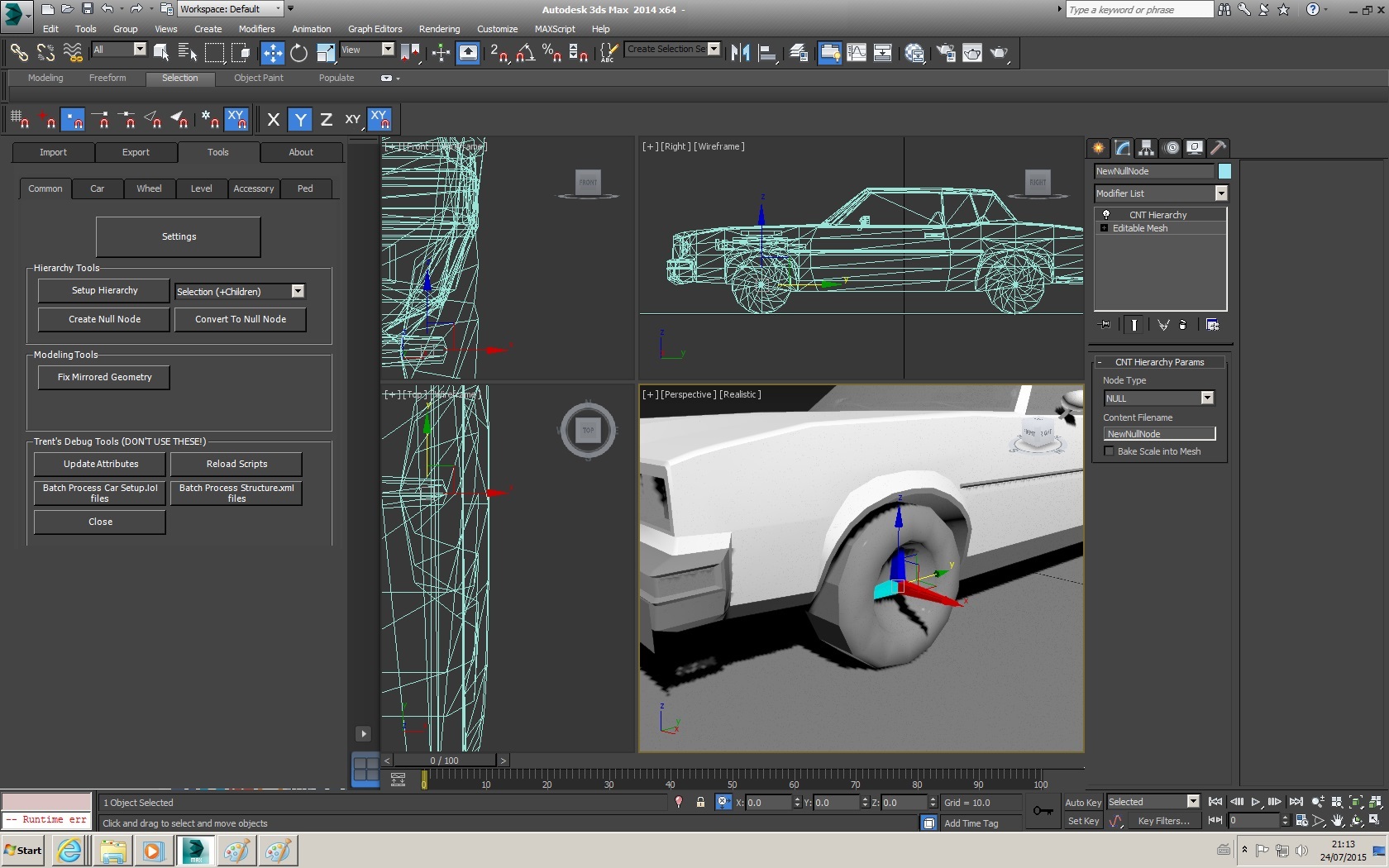
With the wheels in place and setup, the next step is to set the size of them. This can be done by eye using the scaling function, but there is a considerably more accurate method.
Set Wheel Radius To Position:Navigate to the ‘Tools’ -> ‘Car’ Section, and under the ‘Wheel’ Tools, you will see a ‘Set Wheel Radius to Position’ tool. Select each wheel individually and then activate this function. It will scale the radius of the selected wheel to the correct size (using the current Y axis position), so it will touch the ground.
Set Wheel Position to Radius:Under the same menu as the above, this does the opposite of the above function, it will move your wheel in the Y axis (using the current radius) until the wheels touch the ground. It is unlikely that you will need to use this.
Wheel Width:If your wheels are not the desired width, you can alter this with manual scaling in the X axis. If you accidently end up scaling the whole wheel, you can set the radius back to the correct size by re-using the ‘Set Wheel Radius To Position’ method.
________________________
The engine is last part to setup for this basic car. The engine is a non-crushable part, and will need a crushability value of zero.
Render Level:Basic Settings:- Enable Crushability and set to 0.0
- Enable Resiliance and set to 1.0
Physics Properties:Engine Weld:As the engine is a physical model, versus the null nodes used for the Hubs & Wheels. Actual vertices in the part will need to have their vertex colour set to the colour specified in the weld (standard weld value is RGB 0,255,0). But since the Engine is a Non-crushable/Solid Part, and the body is crushable – the engine weld can only have one vertex in it.
Reason for this:
If you were to weld a part that cannot deform to a deformable part at more than one point, as the deformable part deforms, you would have to deform the non-deformable part, and in doing so defy the entire point of it being non-deformable.So with that in mind:
- Select the 'Editable Mesh' modifier
- Go to vertex level
- Select 1 vertex
- Set the vertex colour as Green (RGB 000,255,000)
Then setup the weld appropriately. I usually use a weld strength of -4 or -5 on the engine of a regular car.
________________________
Some final notes on welds:- when welding non-crushable parts to crushable parts, or indeed any parts, the weld vertex doesn’t have to actually meet any vertices on the ‘Weld Partner’, although it will help if it does
- when welding Crushable parts to Crushable parts (for example: bumper to body), the weld vertices (You can have more than 1) MUST meet actual geometry on the ‘Weld Partner’
- Crushable parts cannot be welded to non-crushable/Solid parts, if you do – the game will make the crushable parts solid when loading an event
________________________________________________________________________________________________
The 'Trailer_Hitch' will typically have the following settings
Render Level:Basic Settings:- Enable Crushability and set to 0.0
Physics Properties:Hitch Weld:- Weld to Parent part (c_Body)
- Do NOT set a weakness value
Lastly, the trailer hitch function will have to be set manually by pasting the following command:
CDamageParameters:Set_TrailerHitch( 0, 0, 0, 1 )
into the '' section for the 'Trailer_Hitch' within the structure.xml. This will be covered in chapter 5.
________________________________________________________________________________________________